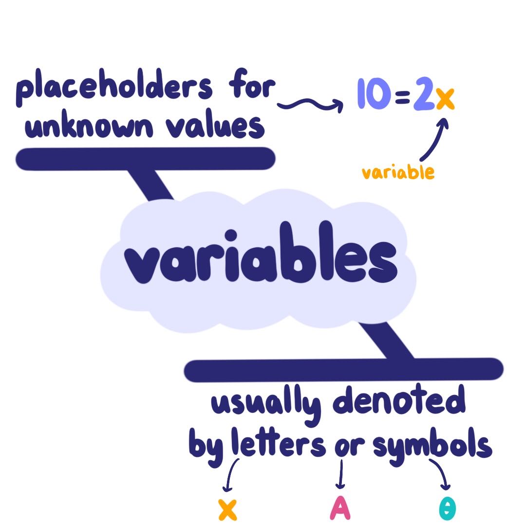
What Are Variables? Definition Amp Examples - Expii
About Variable Timing
So, the engine will have valve timing more suitable for one particular engine speed which is generally at around 50 to 60 of the engine's maximum speed. Therefore, the variable valve timing results the increased combustion efficiency at the selected engine speed. variable valve timing for four cylinder engine diagram. Variable valve timing
A valve timing diagram is a graph that shows the relative timing of the valves opening and closing in an internal combustion engine. Variable Valve Timing VVT represents a significant advancement in improving engine performance, independent of power or torque, following the widespread adoption of multi-valve technology in engine design.
Intake-valve timing The BMW inline-six's intake-camshaft phaser can shift the cam profile by up to 70 degrees, but the opening duration of 255 degrees is fixed. The dwell translates to a total
Continuously variable timing and lift. Complex and large Lotus Active Electro-Hydraulic Valves Continuously variable lift and timing No springs Expensive 1000 per valve ESP can also generate graphs of the mass flow rates. ESP and Valve Timing The picture above show the valve control options in ESP Now lets examine some
Engine efficiency is one of the key aspects to reduce CO2 emissions. In order to improve the emission maintaining high performance capabilities several devices are introduced in the system variable valve timing technology allows more flexibility for modern engines to meet peak performance, fuel economy and low emissions targets 7 while providing good driveability.
Variable Valve Timing for Poppet Valve Systems The traditional camshaft consists of cam lobes which operate the valves figure 1a. The camshaft is timed to the crankshaft through a timing belt. The timing of valve events cant change with RPM. Therefore, during manufacture, the cam lobes are shaped valve lift, dwell and positioned
The system is composed by a variable cam phaser, oil control valve, solenoid and its driver, crank and cam position encoder, and phase controller. Figure 5 Scheme of Variable Valve Timing system The oil control valve, see Fig.6, used is a four-way and two-position spool valve that directs the engine oil flow toward the front or rear rotor chambers.
This plug-in allows you to check the injection timing setting on a VE TDI engine NOT PD or CR varieties. This needs to be done after you change the timing belt and should be done every once in a while to keep tabs on belt stretch and pumppulley misalignment. The standard procedure for this is to have the engine idling at operating temperature coolant temp gt85C, go to measuring block 000
variable valve timing and lift VTEC Engine for the Honda NSX,quot SAE Technical Paper 910008,doi10.4271910008. 2 Lancefield T,Gayler R,and Chattopadhay A,The Practical Application and effects of variable event valve timing system quotSAE Technical paper 930825,1993,doi10.4271930825.
equivalence between the dashed sections of the graphs and the real power sections of the modeled system the scalar product of the two power section variables has the meaning of the Figure 5 Scheme of Variable Valve Timing system The oil control valve, see Fig.6, used is a four-way and two-position spool valve that directs the engine oil


